|
The application of VFDs in paint spray booths
by Mike Olson and Dave Polka
Energy savings is one of the key ingredients in the reduction of costs for any manufacturing operation. Much has been written about energy reduction in fan applications. VFDs (Variable Frequency Drives) provide the adjustable motor speed that reduces energy consumption. The use of industrial robots in paint-spray-booth applications provides an efficient means of applying paint, with great accuracy and little waste. If the combination of variable motor speed, industrial robots and energy management were in one package, a highly cost-effective industrial system would result.
The paint-spray-booth application
Before the details of the VFD system are reviewed, it would be wise to look at an overview of the requirements of a paint-spray-booth. There are numerous types of spray booths. Basically, all booths have several common requirements:
1. The need to control booth pressure. Some paint booth systems are designed to keep a slightly positive pressure inside the booth. This reduces the possibility of dirt or contaminants entering the booth from the outside atmosphere. Other systems are required to maintain a slightly negative pressure, to prevent paint vapors from escaping from the booth and contaminating other work areas. Systems may also employ a combination strategy for changing conditions such as the opening and closing of the booth doors.
2. The need for various fan speeds or flows. For example, as filters become loaded with dirt and paint over spray, the pressure drop across the filter is increased. The fan may then be required to increase in speed, to overcome the increased pressure drop.
3. The need for increased energy savings. As energy costs continue to rise, a more efficient means of static pressure control is desirable. Compared to outlet damper control or other methods of flow control, variable-speed control saves a substantial amount of electrical energy.
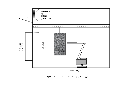
Figure 1 indicates a typical paint spray booth application one in which no flow control is used.
For a positive-pressure-designed painting process, the paint robot sprays the product as part of its normal operating cycle. As previously indicated, a slightly positive pressure is required in the paint chamber. This reduces the input of contaminants into the chamber. The difficulty, however, is in controlling the booth pressure while moving product through the chamber. Product enters and exits the chamber on a regular basis. When the chamber doors open, air pressure within the chamber is reduced. In a constant-flow system, the amount of supply air remains the same, which increases the chances of negative pressure when the doors are opened, adversely affecting the process.
In a typical positive-pressure example -- manual product spray booth -- 5,000 CFM is supplied: 4,500 CFM is exhausted, while 500 CFM is lost through any small leaks and serves to keep the booth at a slightly positive pressure. Total airflow of the system is 5,000 CFM; however, there is no control over the pressure in the chamber and, as a result, the quality of the spray action may be reduced when the doors are open.
VFD control improves product quality
In a VFD-controlled system, the VFD would increase the speed (and thus the supply air CFM) to compensate for the loss of air through the open doors. The automatic paint spray booth improves product quality, by automatically adjusting for losses in chamber pressure. The control system typically monitors a pressure differential. One pressure sensor is located within the paint booth, and another sensor is located externally. These transducers input a differential pressure to an external set-point controller or the VFDs on-board PID (proportional integral derivative) controller. Figure 2 indicates an automatic spray booth process.
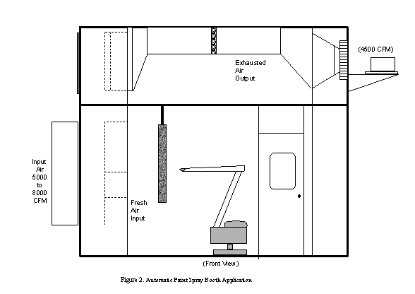
As seen in the figure, the process is identical to the manual system. The difference is in the control of the chamber pressure. The heart of this automatic system lies with the variable frequency drive control of the fan motor. The operation of this device will be discussed later in this article. For now, it is sufficient to say that the fixed-speed-fan operation in the manual system is replaced by a variable-speed-fan operation in the automatic system.
For example, the amount of supply air in this system could be increased to 8,000 CFM. The amount of exhaust remains at 4,500 CFM, with approximately 2,500 CFM escaping through the open doors. By increasing the speed of the supply fan, the booth will remain at slightly positive pressure. The advantage of this system is the ability to increase the supply airflow, to compensate for a loss of air pressure, when the chamber doors are open.
In addition to booth pressure control, a variable-flow system allows for automatic compensation for filter loading. As the paint booth filters become dirty (loaded), the pressure drop across the filters increases. To keep a constant flow or pressure downstream of increasingly loaded filters, the VFD system simply increases the speed of the fan to compensate for the pressure drop across the filter.
Although oversimplified, these examples serve to illustrate some of the most common methods that utilize VFDs in paint booth applications.
Curing process precise air control
Once paint has been applied to the product, the paint must be cured in a curing oven. Figure 3 indicates this process.
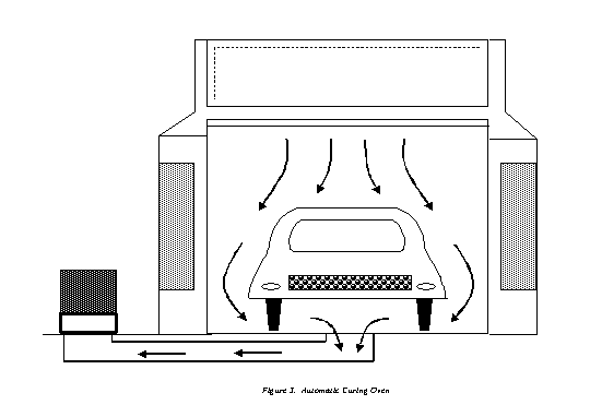
The hot air used to cure the product must be free of outside contaminants that could affect the finish. Once heated, this clean air is forced down toward the product at a constant rate. The balancing of airflow during the curing cycle is accomplished with pressure sensors feeding a set-point controller. The set-point controller output moves actuators connected to balancing outlet dampers that automatically controls exhaust-air volume or booth-differential pressure.
VFDs vs. outlet dampers
An opportunity for energy savings lies in the use of a variable frequency drive control rather than outlet dampers. During the use of outlet dampers, the pressure within the system actually increases, in order to restrict the amount of airflow needed for the process. Figure 4 indicates this characteristic.
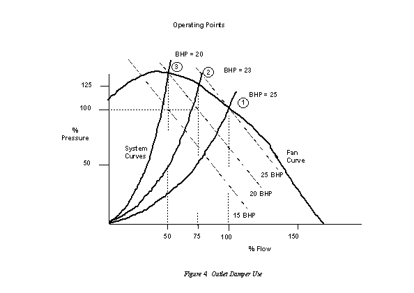
The fan curve represents the pressure and flow-producing characteristics of a given fan. The system curve represents the physical air distribution system, including the sheet metal ductwork, filters, balancing dampers and the fan outlet flow control damper mechanism.
Point one represents full flow with the outlet damper in the full-open position. In the example shown, this corresponds to approximately 25-brake horsepower (BHP) in energy required. Point two represents a condition with the outlet damper partially closed. While the flow (CFM) decreases, the pressure actually increases on the primary side of the control damper. However, due to pressure loss across the outlet damper, the pressure downstream of the damper decreases. This pressure/flow condition corresponds to approximately 23 BHP of energy required. Finally, point three represents further closing of the outlet control damper with the corresponding flow decrease and increasing head across the nearly fully closed damper. This pressure/flow condition corresponds to approximately 20 BHP of energy required.
As indicated in the figure, as less airflow is required by the system, the outlet dampers must close to a level that restricts the output. If 75 percent airflow were required, the pressure in the system ahead of the damper would rise to approximately 125 percent. The fan, which continues to operate at rated speed, now has to work harder, for less airflow output to overcome the loss of head pressure across the damper.
This control method is sometimes referred to as riding the fan curve. As shown if figure 4, outlet damper control and riding the fan curve results in a small reduction in BHP at the reduced flow rates. This method of control can be compared to driving a vehicle with one foot on the accelerator and the other foot on the brake. Its literally supplying energy (kW) to the fan to develop pressure, only to bleed the pressure off with the head loss across the restricting outlet damper.
VFDs avoid traditional accelerator-and-brake control; provide optimal energy usage
A much more efficient system would employ a variable frequency drive to operate the fan motor. In a VFD system, the speed of the fan motor is reduced, thereby reducing the amount of airflow. Simply locking the outlet dampers at fully open position and supplying a VFD can retrofit an outlet damper system to a variable speed system (Note: A better solution is to remove the outlet dampers, as even fully open dampers have some associated head drop across the device.).
The electrical signal (0-10 VDC, 4-20 ma, etc.) that was used to control the damper position can now be used as the speed reference signal for the VFD.
With variable speed operation, each speed represents a different fan curve. Running a fan at reduced speed produces a new fan curve or map roughly parallel to the full-speed design curve. From the Affinity Laws (also called Fan Laws), we know that fan output CFM is directly proportional to the speed of the fan. Static pressure is proportional to the fan speed squared, and fan-required HP is proportional to the fan speed cubed. The Affinity Laws are shown mathematically below, and graphically in Figure 5.
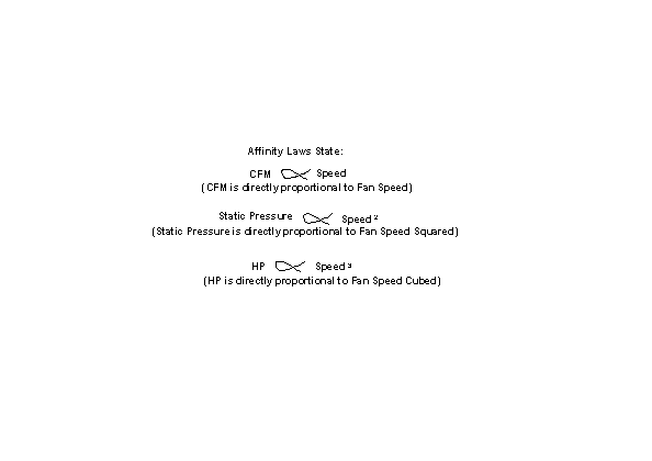 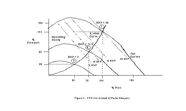
If 75 percent airflow was required, as in the previous example, pressure in the system would be reduced to approximately 50 percent, not 125 percent, as noted earlier. The motor doesnt work as hard, and energy is saved, because the fan speed is reduced, to produce a corresponding airflow. According to the Affinity Laws of pressure, horsepower and speed, to produce 50 percent airflow, only 12.5 percent of rated horsepower is required. This can achieve and yield a tremendous amount of energy savings, if the system is operated at 50 percent to 75 percent airflow, for half or more of its operating period. Figure 6 summarizes the type of energy savings (reduced power consumption) that can be realized using a VFD.
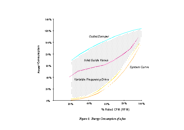
The use of a VFD provides dramatic savings over outlet dampers, in regard to power consumption. Power consumption savings can be dramatic, too, with VFD retrofits of paint spray booths that utilize inlet guide vanes. One automotive manufacturer, as an example, saved 56,200 KWH per year, by installing a 45 KW (60HP) AC drive. The manufacturer also realized more stable process control, less CO2 emissions and improved paint quality.
The shaded area between the curves (in Fig 6) represents the potential savings. The System Curve is the theoretical Affinity Law energy required. Because VFDs use power-switching devices, we can never get completely to the theoretical curves. However, modern VFDs are very efficient, (about 97.5 percent or better) and the difference between the calculated theoretical and VFD curves is very small.
Note, too, that, since VFDs are electronic, they have the capability to accept electric signals from sensors, mathematically process those signals like a computer, and control the speed of a motor simultaneously. This is done via PID control. The complexities of PID are beyond this article, but a simplified explanation will shed light on the use of VFDs in paint-spray-booth applications.
Use of PID (cruise) control
Simply put, a PID loop in a variable frequency drive is similar to the cruise control in an automobile. In an auto, a speed is set in the cruise system. The engine automatically increases or decreases speed, to meet that setting. The cruise system receives an actual speed signal from a wheel sensor that translates rotating speed into an electrical feedback signal. The cruise system compares the speed set by the driver, with the feedback signal from the wheel sensor. The cruise system then decides if the engine should speed up or slow down to maintain set speed, and then executes the command.
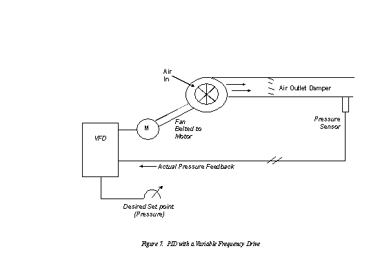
Many modern VFDs have exactly the same capability. Figure 7 indicates a simple PID system, using a variable frequency drive to control airflow.
The operator sets a pressure set-point into the VFD. The feedback-pressure sensor sends the actual pressure signal back to the VFD, where it is compared to the operators set point. The VFD automatically makes the needed speed corrections in order to maintain the desired system pressure. The role of the VFD is to maintain a constant pressure, by varying the speed of the fan. All the pressure control processing is accomplished in the VFD, with no other computing system needed. The operator decides what constant pressure needs to be in the system, for optimum control of the process.
VFDs also excel at controlling variable speed conveyor. Many processes can be optimized, if the correct temperature and speed are used as in a product paint-curing oven.
Precise control of conveyors in the oven optimizes paint
In order to optimize the paint process, a curing oven is often used. It would contain an oven conveyor that would move the product through the curing cycle much like that shown in Figure 8.
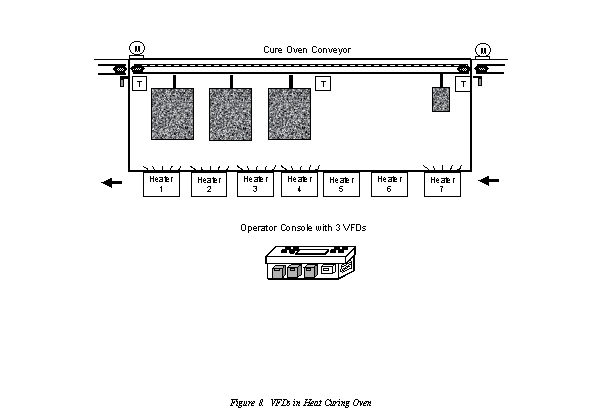
As seen in the figure, an operator, using an operator console, could manually control the oven. However, as it is in many cases, the process is automated by means of a PLC (programmable logic controller). This PLC is connected to several inputs and outputs (i.e. bar code sensors, VFDs and heaters). The PLC is programmed to receive bar code inputs as to the size and how many products are entering the oven. It also gives the speed command to the VFDs, switches on/off heaters as required, and monitors temperature sensors (T). Less heat and faster conveyor speed can be used for smaller products to be cured. When programmed, the PLC and VFDs interact with information, and the correct conveyor speed and oven temperature result in high quality product, no matter what the size or quantity of product.
So what is a VFD (Variable Frequency Drive)?
We have reviewed how the VFD can easily fit into paint spray booths and supporting applications. However, what a VFD is may be a bit fuzzy. A brief tutorial below answers this question.
A motor drive (typically called a variable frequency drive or VFD or AC drive) controls the speed, torque, direction and resulting horsepower of a motor.
Application as an example
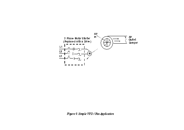
Figure 9 should look somewhat familiar at this point. This is a simple application with a fixed-speed fan using a motor starter. You could replace the three-phase motor starter with a Variable Frequency Drive (VFD) to operate the fan at variable speed. Since you can operate the fan at any speed below its maximum, you can vary airflow by controlling the motor speed instead of the air outlet damper.
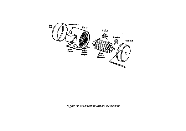
A drive can control two main elements of a three-phase induction motor: speed and torque. To understand how a drive controls these two elements, we will take a short review of AC induction motors. Figure 10 shows the construction of an induction motor. The two basic parts of the motor, the rotor and stator, work through magnetic interaction. A motor contains pole pairs. These are iron pieces in the stator, wound in a specific pattern to provide a north-to-south magnetic field. When energized, the stator magnetic field interacts with the rotor magnetic field, and rotation is the result.
Several items regarding motors should be included here, ahead of explaining how the VFD causes the shaft to rotate. In theory, almost any VFD can be applied to any AC three-phase induction motor. In practice, several items must be kept in mind.
First, the existing fan can remain, but an energy-efficient motor is recommended in VFD applications. System efficiency (sometimes referred to as wire-to-shaft efficiency) is obtained by multiplying the drive efficiency times the motor efficiency. Also, only motors specifically designed for VFD applications are recommended for long motor lead lengths. NEMA describes these as MG1-part-31-compliant motors. It is also best to place the motor as close to the VFD as practical. In most cases, inverter-duty-rated motors can be placed up to 300 feet or more from the VFD, without any additional protection devices.
If the application has an existing motor, the manufacturer should be consulted for acceptance of VFD output. The manufacturer may recommend an add-on filter to be connected to the output of the VFD if the motor leads are exceptionally long or if a non-inverter duty motor is used.
The speed of the motor is determined by the frequency applied to the motor by the VFD and the number of poles designed into the motor. The actual shaft speed is determined by inserting numbers into the formula (shown in Figure 11).
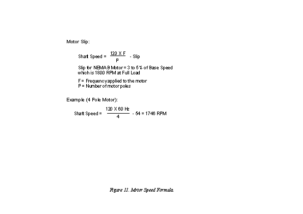
Slip is required for shaft rotation. It varies from motor to motor, but is always required to produce rotation. We can conveniently adjust the speed of a motor by changing the frequency applied to the motor.
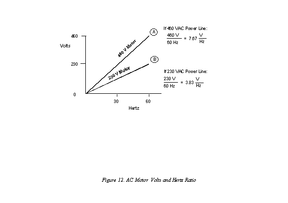
Figure 12 shows how a VFD controls the amount of torque (twisting motion) developed by the shaft. An existing fan, connected across the power line, would see voltage and hertz ratios of those shown in the figure for 230 (point B) or 460 volt (point A) rated motors (e.g. 60 Hz in the U.S.). When a VFD is connected to the motor, it provides the same ratio of voltage and Hz that the power line would provide. Therefore, the ability of the motor to produce rotation and torque is not compromised, when a VFD is connected.
How a drive changes motor speed
Just how does a drive provide the frequency and voltage output necessary to change the speed of a motor? Figure 13 indicates the electronics needed to accomplish that feat. All pulse width modulated (PWM) drives contain these main parts, with subtle differences in hardware and software components.
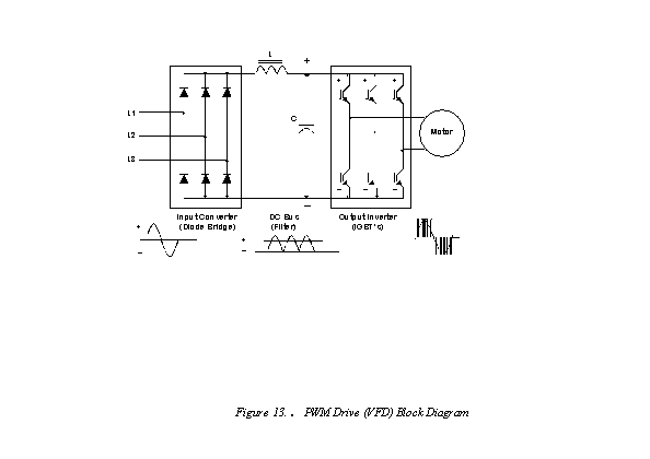
A thorough understanding of the electronic components is not important only how the VFD accomplishes variable frequency output.
The input section of the drive is called the converter. It contains power components that convert AC power to DC power. The next section -- the DC Bus section -- is supplied a fixed DC voltage by the converter.
The DC Bus section filters and smoothes out the waveform: the inductor (L) and the capacitor (C) work together to filter out any AC component of the DC waveform; the smoother the DC waveform, the cleaner the output waveform from the drive to the motor.
The DC Bus feeds the final section of the drive: the inverter. As the name implies, this section inverts the DC voltage back to AC. But it does so in a variable voltage and frequency output. It accomplishes that task by means of power transistor technology, such as the newer, fast-switching devices called IGBTs (insulated gate bipolar transistors).
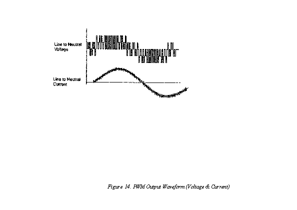
It is hard to imagine, but the output of the VFD actually looks like that pictured in Figure 14. The VFD synthesized AC waveform is actually superimposed on the series of pulses provided by the drive. These pulses are what gives the AC drive the term PWM (pulse width modulation) and refers to the technology of power conversion, as well as the type of output available.
Shrinking cost and size
Drives vary in the complexity of their designs, but the designs continue to improve. Drives come in smaller packages with each generation. The trend is similar to that of the personal computer. More features, better performance and lower cost with successive generations. Like computers, drives have dramatically improved in their reliability and ease of use. However, unlike computers, some drives today dont spew gratuitous harmonics (distortion of utility power) into your AC distribution system. PWM drives also improve your power factor (the efficient use of the utilitys power). Drives are increasingly becoming plug-and-play. As electronic power components improve in reliability and decrease in size, the cost and size of VFDs will continue to decrease. While all that is going on, their performance and ease of use will increase.
Can a VFD be a retrofit item?
One of the advantages of a variable frequency drive is its ability to be installed (retrofitted) into an existing conveyor or fan application. The sizes of VFDs have been reduced in recent years, due to the technology involved. The requirements are that a VFD must be installed in an environment that is clean, dry and within
40 C (104 F) normal maximum operating temperature. It must also be able to supply enough amperes (nameplate motor Amps or FLA) to satisfy the motor at full load. The motor and drive nameplates need to be consulted prior to installation. In other words, the VFD must have an Amp rating equal to or greater than that of the motor.
Structurally, the mounting surface for a VFD must be able to support the weight, and not be exposed to excessive vibration. A 15 HP VFD, for example, would weigh approximately 20 lbs and have a dimension of 5 inches wide by 17 inches tall by 9 inches deep and could easily fit into an operator console, as shown in figure 8. The cost of a 15 HP VFD would be under $2,000, making it possible for paybacks due to energy savings, between six-to-18 months in many cases. A 50 HP unit would double in size, and be approximately three times the weight and the cost with corresponding paybacks a bit shorter. Larger horsepower applications consume more kilowatts and, therefore, payback times are typically shorter the larger the fan (or pump) motor. A VFD representative could estimate, through energy-savings calculations, the money saved via VFD operation, as well as the anticipated payback six months, 12 months, etc.
Besides energy savings, there are additional advantages to retrofitting paint booth, fan or conveyor applications. Consider how reducing stress on the motor affects the motor and equipment positively. First, there is less initial in-rush current (Amps) when a drive is used. (When motors are connected across the power line, they draw 600 percent of rated amps for a short period of time. With an AC drive, however, the initial power shock to the electrical system, and motor, do not take place.)
And, second, the fan can be gradually accelerated to speed by using a drive. (When started across the line, a motor develops a sizeable torque that causes excessive wear on the fan belt, whereas a gradual acceleration from a drive prolongs the useable life of the belt or mechanical system, as well as the motor and fan bearings.) Just as in applying any technology, there are some precautions that need to be addressed, when applying VFDs. However, the payback in energy savings, improvement in process control and quality, and the ability to interact with automated equipment, typically make a VFD purchase well worth the investment. Finally, many local electric utilities offer rebates to help pay for some of the initial investment of installing VFDs on fans and pumps.
Back to top
Back to Web-exclusive articles archives
|