|
Keep your (barrier) guard up!
Devices can safeguard a point-of-operation hazard
Barrier guards are usually the first point-of-operation safeguarding method considered for machines operating in the continuous or automatic single-cycle operation mode. When choosing a barrier guard as the primary point-of-operation safeguard, its design, construction, application and adjustment must comply with OSHA’s 29 CFR, Subpart O, 1910.217 guard requirements. These rules are specific for guards on mechanical power presses; however, the same requirements apply when using guards on other types of machines.
Of the seven guard requirements in OSHA’s 29 CFR, 1910.217 Section (c), the two that industry fails to comply with most often are:
(a) [Guards] shall prevent entry of hands or fingers into the point of operation by reaching through, over, under or around the guard;
(b) [Guards] shall conform to the maximum permissible opening of Table O-10.
Hairpins are used on many guards to comply with these requirements. Simply adjust individual hairpins up or down to conform to each machine application depending on the machine’s configuration and the requirements of material feeding. The U-shaped hairpins are usually made of steel for durability and are secured to the guard with a fastener, T-nut and clip ). Use of the fastener, T-nut and clip makes adjustment quick and easy. Loosen the fastener with a tool and slide the hairpin through the clip assembly.
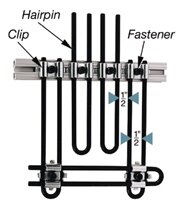 A half-inch opening exists in the hairpin and between hairpins (left), which complies with OSHA’s maximum permissible opening of Table O-10, provided the adjustable portion of the guard is installed at least 2-1⁄2 inches from the point-of-operation hazard. A half-inch opening exists in the hairpin and between hairpins (left), which complies with OSHA’s maximum permissible opening of Table O-10, provided the adjustable portion of the guard is installed at least 2-1⁄2 inches from the point-of-operation hazard.
Use clips to connect horizontal and vertical hairpins to each other if an opening is created when going around obstructions on the machine, or to accommodate strip or coil feeding, conveyors or chutes.
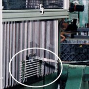 The horizontal hairpins close the opening (right) to ensure the guard meets the O-10’s permissible openings. The horizontal hairpins close the opening (right) to ensure the guard meets the O-10’s permissible openings.
In the construction of a guard, attach hairpins on the top portion of the extruded aluminum frame to form a roof section over the point-of-operation hazard. Attach hairpins to the bottom portion of the extruded aluminum to form a floor section. The roof section prevents someone from reaching over the guard; the floor section prevents someone from reaching under the guard. To prevent reaching around the guard, attach either hairpins or another panel to the vertical portion of the framework to close off the openings between the guard and machine.
When choosing adjustable barrier guards as the method of safeguarding the point of operation, adjustments (using a tool) should be made only by authorized personnel knowledgeable of guard requirements.
|
Table O-10
|
Distance of opening from point of operation hazard
(in inches) |
Maximum opening width (in inches) |
1/2 to
1-1/2 |
1/4 |
1-1/2 to
2-1/2 |
3/8 |
2-1/2 to
3-1/2 |
1/2 |
3-1/2 to
5-1/2 |
5/8 |
5-1/2 to
6-1/2 |
3/4 |
6-1/2 to
7-1/2 |
7/8 |
7-1/2 to
12-1/2 |
1-1/4 |
12-1/2 to
15-1/2 |
1-1/2 |
15-1/2 to
17-1/2 |
1-7/8 |
17-1/2 to
31-1/2 |
2-1/8 |
OSHA’s Table O-10 (at right) shows an opening’s maximum width or height based on the distance the opening is from the point-of-operation hazard. Use a guard opening scale to check openings once the guard is installed. This tool simulates the openings of Table O-10.
After installing point-of-operation guards and before releasing each job for operation, use the scale to verify openings comply with Table O-10.
Article provided by Rockford Systems Inc., a manufacturer of machine controls and safeguarding products. For more information or to receive the On Guard! newsletter, call , or visit www.rockfordsystems.com.
Back to top
Back to Web-exclusive articles archives
|